Cutting tool terminology with detailed explanation
The cutting tool is the key element in machining where metal removal is required for whatsoever reason. For best output and optimum performance with minimum efforts and work input, the cutting tool is designed in a specific way. There are various terms associated with the design of the cutting tool. Here is cutting tool terminology with detailed explanation.
Cutting tool terminology
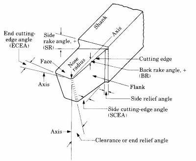
Back rack angle
- In cutting tool terminology, it is the angle between the line parallel to the tool axis passing through the tip and the rack face.
- The angle is measured in a plane perpendicular to the base
- For brass, back rack angle will be zero.
- Positive back rack angle is used for soft and ductile material while negative back rack angle is used for hard and brittle material.
Side cutting edge angle
- It is the angle between side cutting edge and the line extending the shank.
- The angle is measured in the plane perpendicular to the base.
- Feed represents uncut chip thickness
- The depth of cut represents the width of the chip.
Side rack angle
- It is the angle between the rack face and the line passing through the tip perpendicular to the tool axis.
- The angle is measured in a plane perpendicular to the base
- Value of the angle varies from 5 to 15
- Large positive rack angle results in less chip formation, less cutting force, good surface finish and low heat dissipation rate.
Side relief angle
- It is the angle between the side flank and the line passing through the tip perpendicular to the base.
- The angle is measured in a plane perpendicular to the tool axis.
- Value of the angle varies from 5 to 15
- Side relief angle is provided to prevent side rubbing after elastic recovery of the workpiece.
End cutting edge angle
- It is the angle between the end cutting edge and the line passing through the tip perpendicular to the tool axis.
- The angle is measured in a plane parallel to the base.
- Value of the angle varies from 8 to 15
- Small end cutting edge angle results in tool chatter
End relief angle or clearance angle
- It is the angle between nth e end flank and the line passing through tip perpendicular to the base
- The angle is measured in plane parallel to the tool axis
- In the ductile material large end relief angle is provided due to more elastic recovery
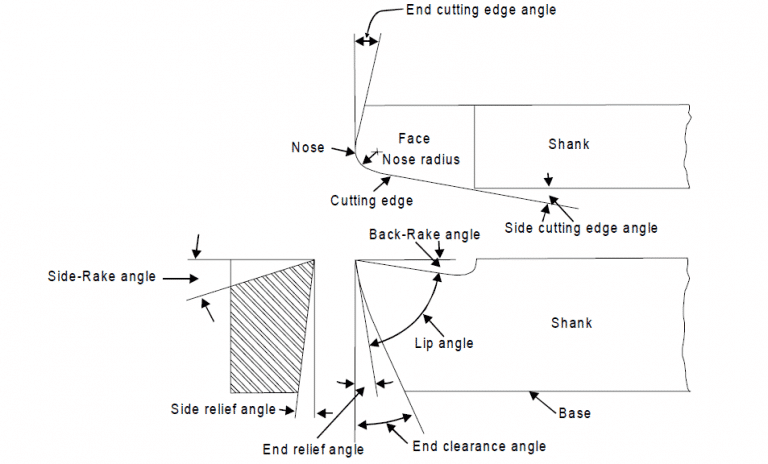
Nose radius
- Nose radius provides long tool life and good surface finish.
- Large nose radius results in more power consumption.
Tool signature
There are two types of tool signature in cutting tool terminology.
-
ASA tool signature
BR-SR-ER-SRF-ECEA-SCEA-NR
-
Orthogonal rack system
Angle of inclination- normal rack angle – side relief angle- end relief angle- end cutting edge angle- approach angle
This is all about cutting tool terminology.
Subscribe
If you enjoyed this article, subscribe to receive more just like it.


Very instructive and excellent structure of written content, now that’s user pleasant (:.